UNIFACE and the N-Tier Architecture
Tony Marston - 31st May 2000
Version 2.0
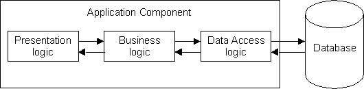
1. The 1-Tier Structure.
A component in a 1-Tier structure contains all the code necessary to deal with the user interface, the data validation, and all communication with the physical database. Where several components access the same data objects (files, tables or entities – whatever you want to call them) there can quite a bit of duplication. Apart from having to spend extra time in the first place to create components with similar code it also means that any subsequent changes to data objects or business rules would then require the same code changes to be replicated in what could turn out to be a large number of components.
Each new methodology always distinguishes itself by using new words for old ideas, so as I am from the ‘old school’ I use the following translation table:
A component based on the 1-Tier structure can therefore be represented in the following diagram:
Figure 1- The 1-Tier Structure
2. The 2-Tier Structure.
In a 2-Tier structure the logic is split into two tiers (or layers), usually done by splitting off the data access logic. This results in the following structure:
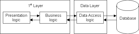
Figure 2 - The 2-Tier Structure
This removes all the complexities of communicating with the database to a separate layer. It should therefore be possible to switch to a different database system just by changing the contents of the data layer. Provided that the operations and signatures with the 1st layer remain consistent there should be no need to modify any component in the 1st layer.
2. The 3-Tier Structure.
This splits each of the three logical areas into its own layer. For this structure to work effectively there should be clearly defined interfaces between each of the layers. This should then enable components in one layer to be modified without requiring changes any changes to components in other layers. One example is changing the file system from one DBMS to another, or changing the user interface from one system to another (e.g. from client/server to the web).
The main advantage of this structure over the 2-Tier system is that all business logic is contained in its own layer and is shared by many components in the presentation layer. Any changes to business rules can therefore be made in one place and be instantly available throughout the whole application.
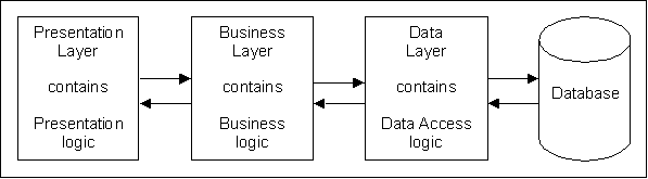
Figure 3 - The 3-Tier Structure
4. Where does UNIFACE fit into this picture?
Uniface was originally designed around the 3-Schema, 2-Tier architecture.
The 3-Schemas are:
The Physical Schema does not exist as a separate object, it is held as entity or field interface definitions within the Conceptual Schema.
A form (ES) is built by defining which entities from the CS need to be referenced, then painting the necessary fields within the boundaries of each entity. When a <read> or <write> trigger is fired control is automatically passed to the database driver which performs the necessary action on the physical database.
This can be represented in the following diagram:
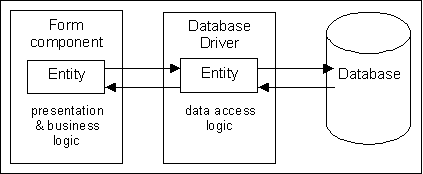
Figure 4 – UNIFACE and the 2-Tier Structure
Since these early days (I started with version 5 in 1992) Uniface has undergone a few changes:
4.1 UNIFACE and the 3-Tier structure.
In order to provide a relatively painless method of splitting the business logic from the presentation logic in the form component Compuware introduced the concept of Object Services in Uniface v7.2.04. The UNIFACE view of the 3-tier structure can be represented as follows:
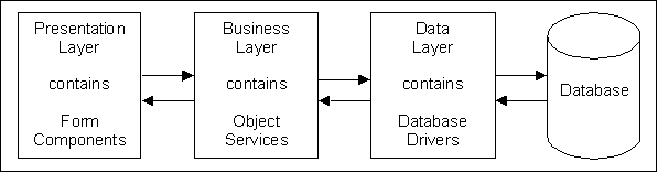
Figure 5 – UNIFACE and the 3-Tier Structure
Each database entity has its own object service in which all business logic can be defined. For certain one-to-many relationships it is also possible to create a single object service for both of those entities. By including the relevant business rules in each object service it means that these rules need not be replicated in any form component. Provided that the form’s access to the database is routed through the object service (there is a data access switch on each entity within each form), the rules within the object service are instantly available to the form. As an aid to performance, if several forms in the same session access the same entity at the same time, they will actually share the same object service for that entity.
As well as having the code for the various rules defined in the field or entity validation triggers within the object service itself it is also possible to move this code into a separate component which is activated from the object service. I have tried both approaches with success.
4.2 Implementation of Object Services.
Compuware have made the process of creating and using object services very, very easy. The procedure is as follows:
For existing form components that were assembled in a 2-tier structure the only change that needs to be made to any code is to move the business logic from the form into the relevant object service. No code needs to be changed in the form in order to communicate with an object service - it is totally transparent. As soon as any database trigger is fired on an entity where the Data Access flag has been set to ‘Object Service’ Uniface will automatically route all activity through that object service.
4.3 Validation via Object Services
The main difference with using business rules in object services is that field validation in the form is limited to declarative checking only. All other validation can only be performed when the <store> trigger is fired. This appears to be a backward step (it reminds me of my days using a block mode user interface with green screens), but it emulates the behavior of forms that are deployed on the web. Forms which are constructed in this fashion will therefore not need massive conversion before being enabled for the web.
If the idea of data validation ‘en bloc’ is not acceptable in a client/server environment there is a method of combining the advantages of object services with the immediacy of field-by-field validation:
In a field’s <leave field> or <validate field> trigger:
call VLDF_OBJSVC($entname, $fieldname)
In an entity’s <leave mod occ> or <validate occ> trigger:
call VLDF_OBJSVC($entname, "")
This then gives you the ability to perform field-by-field validation without having the code embedded in the form. I have produced some working examples of this, so if you would like a copy of my code please contact me using the e-mail address at the foot of this document.
5. What is the N-Tier structure?
The name implies a structure which contains ‘N’ number of tiers where ‘N’ is a variable number, usually larger than 3. This is usually achieved by taking a component in one of the standard layers of the 3-Tier structure and breaking it down into subcomponents, each performing a specific low-level task.
For example, the designers of a project with which I am currently acquainted (sadly) have broken down each of the initial three layers into something which resembles the following:
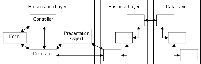
Figure 6 – Splitting 3 layers into ‘N’ layers
The function of each of these components is described in the following table:
|
Form |
Interacts with the user. Uses the Decorator to read and write all data. |
|
Controller |
Controls the flow of a use case, navigating from one form to another in the correct sequence. |
|
Decorator |
Interface between the presentation layer and the business layer. Obtains data for a form and distributes data from a form when updating. |
|
Presentation Object |
Presentation logic for a use case. Used for logic which is specific to a use case rather than a business object. |
|
Business Component Interface |
One per domain or logical group of entities. |
|
Business Object |
Business object for a logical entity. Contains all the business rules for that entity. |
|
Business Service Bridge |
Business component to business component interface. |
|
View |
An indexed list of keys for an object. |
|
Translator |
Translation between the logical data layer and the physical data layer. |
|
Cache |
Holds business data for a use case. |
|
Data Service |
Performs physical database IO. |
The resulting structure may appeal to academics, theoreticians and exponents of the latest fashionable methodologies, but it falls down in one serious respect – it takes far too long to develop usable software. After a team of 6 people spent 6 months in prototyping the time came to build the first real use case. It consisted of two simple screens – one to enter selection criteria and a second to list the results, using a single database table. It took the team 2 weeks. Notice I said ‘team’ (6 people) and not ‘developer’ (single person), giving a total of 12 man-weeks for a simple two-screen use case. Six months later the level of productivity has increased - it still takes 2 weeks per use case, but now with just a single developer.
Having spent a life time in a commercial environment where productivity was always the prime consideration I am used to constructing working transactions in hours and days, not weeks and months. To put things in perspective the last project I worked on (albeit an in-house project) required 50 forms accessing 19 database tables with 18 relationships. Using my own ready-made infrastructure and development standards I designed it in 1 week, then built and tested it in 4 weeks. That’s an average of 2.5 forms per day, but on good days I peaked at 6.
I do not consider the level of productivity from this new N-Tier architecture to be acceptable, and I don’t think that many paying customers would either. The architects of this structure spent too much time in bending UNIFACE to fit their particular interpretation of the rules. This dogmatic approach diverted their attention from the real purpose of software development, which is to produce working programs as quickly as possible. This ‘politically correct’ structure just will not succeed in a competitive market place.
Tony Marston
31st May 2000
mailto:tony@marston-home.demon.co.uk mailto:TonyMarston@hotmail.com http://www.marston-home.demon.co.uk/tony/
Amendment history:
Version 1.0 5th December 1999
Version 2.0 31st May 2000
In the first version I erroneously referred to the original implementation of UNIFACE as being 1-Tier. Everyone knows that it is in fact 2-Tier as all data access is controlled through interchangeable database drivers. I was persuaded by the designers of my new project (who were supposed to be experts) that because these database drivers were ‘sealed boxes’ and not components that could be assembled by the development team according to their own rules that they could not be classed as ‘true’ data layer components. However, having now seen the results of their designs I consider their opinions and abilities to be seriously flawed.