Using
UD6/CMtool Driver and Uniface with PVCS Dimensions
PVCS Dimensions from Merant, provides a complete software
configuration management solution, which is delivered with
a process engine at its heart. Its support includes, parallel
development, distributed engineering, build and release
management, change management, configuration and workspace
management, process management, object and repository management
and incident management..
The home of PVCS Dimensions on the web is http://www.merant.com/products/pvcs/dimensions/
A complete list of configuration management tools can be
found at:
ftp://rtfm.mit.edu/pub/usenet-by-group/comp.answers/sw-config-mgmt/cm-tools
If you have not already done so, please read A
methodology to Uniface source code control before you
continue with these topics and examples.
Using UD6 with PVCS Dimensions
Since UD6 supplies Uniface source code to PVCS Dimensions
in industry standard text files (in XML format), all of
the advanced PVCS Dimensions features can be used to organise
and manage your work. These include Worksets, Products,
Design Parts, and Product items.
UD6/CMtool
Driver is the only CM/SCM solution for Uniface that allows
this level of functionality.
Process Model
Our examples are all based on the default generic process
model provided with PVCS Dimensions. March Hare recommend
that you tailor this model yourself or use either Merant's
or March Hare's consultants to assist in developing a process
model that best fits your organisation.
What
to Version Control
If you are using PVCS Dimensions, March Hare advise that
you use its capacity to manage all files associated with
a Uniface development environment, both source items and
derived items (like .frm, .svc, .rpt and .dol files). You
can also use PVCS Dimensions to manage objects not in the
filesystem, like database objects.
This manual only describes the process of setting up PVCS
Dimensions and UD6/CMtool Driver for versioning your Uniface
source code, since that is the unique ability of the UD6/CMtool
Driver software. To version control derived objects, or
database objects please refer to the extensive documentation
that Merant supply with PVCS Dimensions.
PVCS
Dimensions & UD6 guide
| Next > |
- |
Configuration
Information |
| |
- |
Taking
Control in Dimensions |
| |
- |
Releasing
a form using Dimensions |
| |
- |
Checking
a form in using Dimensions |
| |
- |
Adding
a form using Dimensions |
| |
- |
Finding
the difference in versions using Dimensions |
| |
- |
Problems
when using Dimensions |
Configuration
Information
Here
is a quick overview of the steps to installing and running
Uniface with PVCS Dimensions using UD6/CMtool Driver. Each
step is explained in more detail if you click on the links
that are provided.
- Install
Uniface and UD6/CMtool Driver on to the NT Workstation.
-
Alter the usys.ini and usys.asn files as per the Guide
to Installing UD6/CMtool driver.
-
Alter the usys.asn file to have
a 'catchall' to direct all non-joined source code to the
.\sources\other directory, set the $MAXFILES and set temporary
files to be stored in another database.
-
Start and then close the IDF to initialise an empty repository.
(For the purposes of this demonstration,
the default directory of the shortcut used to start the
IDF should be a temporary directory for loading your existing
source code into the XML format that the UD6/CMtool Driver
uses (we used c:\usys-ud6102\project).
The file c:\usys-ud6102\project\sources\other\udicver.xml
now exists, and contains 1 record.
-
Add the 'nokeycheck', and optionally the 'xmlschema ???'
parameter(s) to the USYS$UD6_PARAMS setting in the usys.asn
file (this setting improves the performance of the UD6 driver
for bulk load operations, and creates XDR information, but
must be disabled for normal use).
-
Load the repository from a backup with a command like:
                      idf /com=100 /cpy trx:7204bkp07Feb2000.trx
                      idf:
(some unix environments may require the /com=10 switch to
reduce the number of file handles used).
- Alter
the usys.asn file to remove the 'nokeycheck' and/or the
'xmlschema ???' parameter(s).
- If
you are upgrading versions of Uniface at the same time as
setting up UD6, and you previously loaded the Uniface Meta-Dictionary,
you will need to delete it and install the Meta-Dictionary
that was supplied with you newer version of Uniface. To
do this perform the following steps:
                      cd sources\tables
del dict-*.xml del ucvs-*.xml
del sysenv-*.xml
del printer-*.xml
cd ..\sub-types
del *-dict-*.xml
del *-ucvs-*.xml
del *-sysenv-*.xml
del *-printer-*.xml
-
Prior to controlling your source in PVCS Dimensions, it
is wise to compile all objects and forms, e.g.:
idf.exe /all
This ensures that all the descriptors have been generated
for the forms. Without this information you will not be
able to compile forms in the CM tool since they will be
read-only and the descriptors cannot be generated (see the
nodeny parameter in the USYS$UD6_PARAMS help topic).
- For
the same reasons you may wish to start up the IDF and select
the Assembly Area, then the Assembly Workbench.
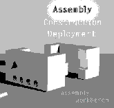
Clicking on this ICON will start the initial synchronisation
of signatures and diagram.

Configuration files
| |
- |
usys.asn
file |
| |
- |
Joins
file |
| |
- |
MultiUSE
file |
PVCS
Dimensions & UD6 guide
| |
- |
Overview
|
| |
- |
Configuration
Information |
| Next > |
- |
Taking
Control in Dimensions |
| |
- |
Releasing
a form using Dimensions |
| |
- |
Checking
a form in using Dimensions |
| |
- |
Adding
a form using Dimensions |
| |
- |
Finding
the difference in versions using Dimensions |
| |
- |
Problems
when using Dimensions |
Taking
Control in PVCS Dimensions
As a way of introducing Dimensions, we'll go through a typical
work-session using it.
At this point your source code is now in XML the format that
the UD6/CMtool Driver uses (in the directory c:\usys-ud6102\projects\sources),
and is ready for 'putting into' Dimensions. The following
describes a Dimensions setup which is a fairly straightforward
one and should suffice for your initial evaluation, or to
give more advanced Dimensions users an insight into the specifics
of using PVCS Dimensions with the UD6/CMtool Driver for Uniface.
Installing
and setting up Dimensions.
-
Install the Dimensions and Oracle server and client software
(all of the commands shown here are executed from the client).
If it is your first experience setting up Dimensions, we
recommend using the default installation procedure, including
using a new Oracle installation and database.
Migration
tasks to be performed.
-
Create a Dimensions product using
the process modeller.
-
Define file formats and MIME types
using the process modeller.
-
Define Object Type Definitions using
the process modeller
-
Create a workset for the product.
.All Uniface source code in our example will be assigned
to the item type (Object Type definitions) SRC.
-
If you are performing these actions on a Windows NT server
which has a PVCS Dimensions server running on it, but you
wish to load the sources onto a different Dimensions server
Set the MCX_SLAVE environment variable to "mcxrelay.exe"
- Configure
MULTIUSE for specifying the location of Reference areas,
Sandboxes and developer INUSE files.
- Upload
the sources to Dimensions using the Data Migration Utility.
- Create
baseline using the PC Client Utility.
Taking Control
| Next > |
- |
Create
a Product |
| |
- |
Define
file formats |
| |
- |
Define
Object Types |
| |
- |
Create
a Workset |
| |
- |
Setup
MULTIUSE |
| |
- |
Upload
sources |
| |
- |
Create
Baseline |
PVCS
Dimensions & UD6 guide
| |
- |
Overview
|
| |
- |
Configuration
Information |
| |
- |
Taking
Control in Dimensions |
| |
- |
Releasing
a form using Dimensions |
| |
- |
Checking
a form in using Dimensions |
| |
- |
Adding
a form using Dimensions |
| |
- |
Finding
the difference in versions using Dimensions |
| |
- |
Problems
when using Dimensions |
Create
a Dimensions Product
A product is the top most item in a PVCS Dimensions database
of things that it manages. Source code, as well as change
requests, documentation etc all belong to a product. You create
a product using the process modeller.
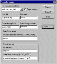
Start
the process modeller, and log in using an account with permissions
to create products.
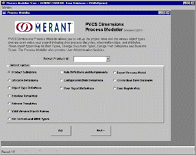
Select the option to Create a product, and press Next.
Define a new product by pressing the Add button and filling
in the correct details. In our example the ID is BRIDAL, based
on $GENERIC, Variant AAAA and version no. of 1. ADMINISTRATOR
is the Product-Manager, Change-Manager and Parts-Controller.
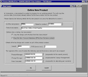
Press OK when done. PVCS Dimensions lets you know when the
product has been created.

Taking
Control
| |
- |
Create
a Product |
|
Next >
|
- |
Define
file formats |
| |
- |
Define
Object Types |
| |
- |
Create
a Workset |
| |
- |
Setup
MULTIUSE |
| |
- |
Upload
sources |
| |
- |
Create
Baseline |
Create
Dimensions File Format and MIME type definitions
File format definitions define types of files that a PVCS
Dimensions project contains, based on the filename extension.
Uniface projects using the UD6/CMtool Driver have files with
the following object types:
XML
XSL
CSS
GIF
However
in a production environment you would usually also include
object file types FRM, SVC, RPT, APS, DOL, URR (these would
all be type: binary, application/uniface).
To
define file types use the PVCS Dimensions Process Modeller.
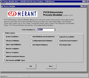
Add
XML, CSS and XSL to File Formats and MIME types using the
process modeller (Object Type Definitions) type=ASCII text
(mime types are text/xml, text/css and text/xsl).
Add GIF to File Formats and MIME types using the process modeller
(Object Type Definitions) type=Binary (mime type is image/gif).

Taking
Control
| |
- |
Create
a Product |
|
|
- |
Define
file formats |
|
Next >
|
- |
Define
Object Types |
| |
- |
Create
a Workset |
| |
- |
Setup
MULTIUSE |
| |
- |
Upload
sources |
| |
- |
Create
Baseline |
Create
Dimensions Object Type Definitions
Object Type Definitions define types of files that a project
contains. In our example we only are using the source type:
SRC (file types XML, XSL, CSS, GIF). However in a production
environment you would usually also include object files OBJ
(file types FRM, SVC, RPT, APS, DOL, URR).
This needs to be associated with individual types of files,
and a directory on the server to store them.
NOTE:
If using a PVCS Dimensions server on Windows-NT, you must
perform this step on the server.
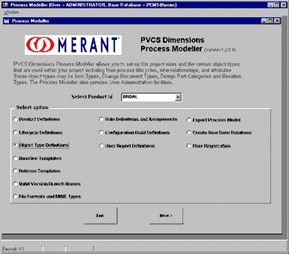
Select
the Object Type Definitions option then press next.
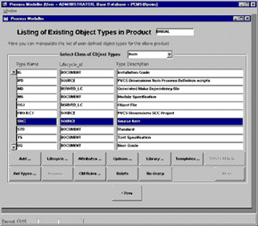
Select
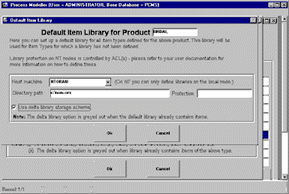
the SRC Type name and press the Library... button.
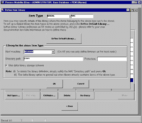
Select
the Delta option, and specify a directory into which PVCS
Dimensions will store the files on the server (e.g.: c:\src).
Press OK when complete.

Press
OK to dismiss the dialog box when complete.
If
you wish to you can also define a library for all other types
by pressing the Library… button again, followed by the
Default Library button, and setting another directory for
non-src PVCS Dimensions files.
Taking
Control
| |
- |
Create
a Product |
|
|
- |
Define
file formats |
|
|
- |
Define
Object Types |
|
Next >
|
- |
Create
a Workset |
| |
- |
Setup
MULTIUSE |
| |
- |
Upload
sources |
| |
- |
Create
Baseline |
Create
a workset
The workset is created using the PC Client utility.
The
developer will use the PC client utility and Windows Explorer
to manage the Uniface source code. The workset is then assigned
to each user and has an assigned "workset root directory".
This is how ud6/CMtool opens and read and writes the Uniface
source code.
The
access to the files (read-only, or read-write) is managed
by Dimensions depending on the access that the developer has
been granted (e.g.: to perform some maintenance). Please read
the PVCS Dimensions PC Client Utility manual (p 6-2, "Workset
Assignment to Users", for more information).
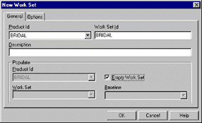
To
create a new workset use the PC Client application, using
the pulldown menu items, File, New, Workset.
Choose
the product that you created in step 1, and set the name of
the workset to be the same as the name of the product. Click
the checkbox 'Empty Workset'.
Create
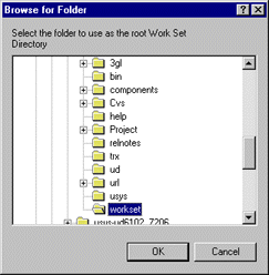
a directory usys72\workset, eg: c:\usys-ud6102\workset.
Use
the pulldown menu to select Workset, Change Directory to choose
a folder in the file system which will reflect the contents
of the workset. We used c:\usys-ud6102.
Use
the pulldown menu to select Workset, Change to choose the
workset that was just created as the default.

Select
the correct project and workset then press the Make Default
button.
Taking
Control
| |
- |
Create
a Product |
|
|
- |
Define
file formats |
|
|
- |
Define
Object Types |
|
|
- |
Create
a Workset |
|
Next >
|
- |
Setup
MULTIUSE |
| |
- |
Upload
sources |
| |
- |
Create
Baseline |
Configure
MULTIUSE
For any chosen PVCS Dimensions PRODUCT/VARIANT/WORKSET combination
a read-only copy of the source code should exist some place
in the file system, so that Uniface developers can compile
dependent work, and browse the code during development and
problem investigation.
When
an individual component is identified as requiring modification,
it is 'checked out' from PVCS Dimensions in the usual manner,
and copied to some place in the file system 'read-write'.
Several
Uniface assignment file parameters and the UD6 JOINS file,
assist the IDF and the UD6/CMtool driver resolve where in
the file system these files exist.
These
parameters are:
| |
[ENTITIES]

                          *.dict $idf:.\sources\other\*.*
[DRIVER_SETTINGS]

                          USYS$UD6_PARAMS=LISTDIR directory/filename
|
The
line shown above in the [ENTITIES] section of the Uniface
assignment file (in conjunction with the file specifications
in the UD6 JOINS file, which is by default located in the
Unfiace BIN directory) specify the location of the reference
area.
For
each reference area an installation typically has a separate
assignment file.
The
LISTDIR setting in the [DRIVER_SETTINGS] section of the Uniface
assignment file indicates the place and filename that contains
the list of 'checked out files' for this user or workgroup.
Installations
typically set this up on a drive letter that is assigned to
a 'share' on the server when a user logs in, dependent on
either their username or group name, e.g.:
| |
[DRIVER_SETTINGS]

                          USYS$UD6_PARAMS=LISTDIR t:\inuse
|
T:
is allocated to the network share \\ntsrvr01\user1.
Or
T:
is allocated to the network share \\ntsrvr01\devel.
An
INUSE file can be named anything, and if a developer works
on many PVCS Projects or Variations you may want to name the
INUSE file accordingly, e.g. this file is for the Project
BRIDAL Variant AAAA:
| |
[ENTITIES]

                          *.dict $idf:m:\ref\brd-aaa\sources\other\*.*
[DRIVER_SETTINGS]

                          USYS$UD6_PARAMS=CONFIG m:\ref\brd-aaa\, LISTDIR h:\brd-aaaa.inuse
|
And
the JOINS file for this example would be (m:\ref\brd-aaa\joins):
| |
UFORM:ULABEL:ULABEL::m:\ref\brd-aaa\sources\components\*

                          UXGROUP:UFORM:ULABEL,UBASE::UFORM

                          UXFIELD:UFORM:ULABEL,GRP,UBASE::UFORM

                          .

                          .
|
When
copying JOINS files to another location be sure to also re-create
or copy the xlink, ofields, nls0, and overflows configuration
files to the same location.
Finally
PVCS Dimensions needs a mechanism to automatically update
the correct reference environment and INUSE file dependent
on the PRODUCT/VARIANT/WORKSET and USER performing a check
out or check in operation.
Since
PVCS Dimensions does not have a scriptable triggers mechanism,
March Hare supply an add-in for this purpose. Using the PVCS
Dimensions server computer, replace the DLL PCMS_ROOT\prog\libpcmsu.dll,
with the file of the same name in your Uniface BIN directory
(this file was installed when you installed UD6/CMtool Driver).
You must also copy the file ud6list.dll from the Uniface BIN
directory to the PCMS_ROOT\prog directory.
The
PCMS_ROOT directory is commonly named: c:\win32app\pvcs\dimensions\6.0.
This
add-in requires that an environment variable be set to indicate
the directory that the MULTIUSE configuration file is located
in. Open the Windows control panel, by clicking on the Start
button, then Settings, Control Panel.:
Within
the control panel open the System control panel.
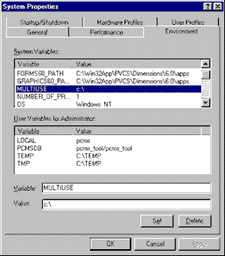
Add
the environment variable MULTIUSE to the SYSTEM environment
variables, and press OK.
Here
is an example MULTIUSE file (c:\multiuse) that matches the
examples used above (Project BRIDAL Variant AAAA, and two
users, user1 and user2):
| |
+R¶¶PRODUCT:BRIDAL¶VARIANT:AAAA¶WORKSET:DEV¶¶d:\ref\brd-aaa\

                          +I¶USER:USER1¶PRODUCT:BRIDAL¶VARIANT:AAAA¶WORKSET:DEV¶¶c:\users\user1\brd-aaaa.inuse

                          +W¶USER:USER1¶PRODUCT:BRIDAL¶VARIANT:AAAA¶WORKSET:DEV¶¶h:\brd-aaa\

                          +I¶USER:USER2¶PRODUCT:BRIDAL¶VARIANT:AAAA¶WORKSET:DEV¶¶c:\users\user2\brd-aaaa.inuse

                          +W¶USER:USER2¶PRODUCT:BRIDAL¶VARIANT:AAAA¶WORKSET:DEV¶¶h:\brd-aaa\
|
When
USER1 or USER2 logs into their workstation drive letter h:
is automatically assigned to their logon directory (server
directory c:\users\usern). The users work-sets are stored
in their 'local' directory h:\brd-aaa\.
It
IS NOT necessary for the 'checked out' files to exist on a
shared drive, since the MULTIUSE DLL does not need access
to the checked out files, it just needs to know what directory
prefix to use when the workstation tries to open it using
the IDF.
The
INUSE file however, MUST exists on a shared drive so that
both the server and the client have access to it. The MULTIUSE
file refers to the INUSE file 'as seen from' the server, whereas
the USYS$UD6_PARAMS=LISTDIR path/file setting refers to the
INUSE file 'as seen from' the client.
Finally,
in order to keep the reference area in 'sync' the libpcmsu.dll
automatically fires off FI (Fetch Item) commands using the
PCMS.EXE utility supplied with PVCS Dimensions. Before proceeding
to the upload stage, be sure to have tested that this works
(it may require that you set the PCMSDB environment variable
to a valid Oracle Username/Password, e.g.: pcms_tool/pcms_tool).

NOTE:
For the 'FI' Fetch Item command to work, and for the 'remove'
command to word when 'DI' Delete Item command is received,
the reference area must be accessible through the same filename
and path on both the server and the client. This is usually
achieved by 'connecting' the shared drives to the same drive
letter(s) on the server as the client.
If
you are concerned about the performance impact of 'connecting'
redundant shared drives using a facility like NET USE, you
can alternatively use the SUBST command, e.g. (commands executed
on node NTORA8I):
| |
NET USE
                          v: \\ntora8i\c-drive
|
Is
functionally the same as:
See
also the subject 'Configuration Files' UD6/MultiUSE
in the help file that comes with the UD6/CMtool Driver software.
Taking
Control
| |
- |
Create
a Product |
|
|
- |
Define
file formats |
|
|
- |
Define
Object Types |
|
|
- |
Create
a Workset |
|
|
- |
Setup
MULTIUSE |
|
Next >
|
- |
Upload
sources |
| |
- |
Create
Baseline |
Upload
the sources
Before proceeding please ensure that you have completed the
steps the article Configure MULTIUSE.
To upload files into PVCS Dimensions, the user must have been
assigned the DEVELOPER role.
The
data migration utility is used to upload the Uniface sources
in XML format generated from UD6/CMtool Driver, to the Dimensions
server. Please read the PVCS Dimensions Data Migration Utility
manual (p 2-5, "Migrating from Operating-System Files
to Dimensions", for more information).
Start
the PVCS Dimensions Data Migration Utility
In
our testing we found it advisable to perform this activity
on the PVCS Dimensions Server (note: you will have to re-select
your Work Set directory in PC Client Utility).
Note:
The script execute phase of this task is extremely memory
intensive for the server process (ifrun60.exe), if necessary
increase the amount of page space available for before beginning
this task.
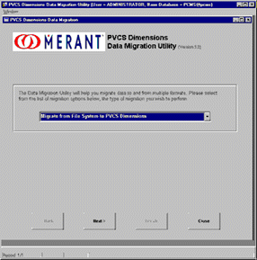
Select
the Object Type Definitions option then press next.

Select
"Migrate from File System to PVCS Dimensions".
Press
Next to continue.
Specify
Upload Details
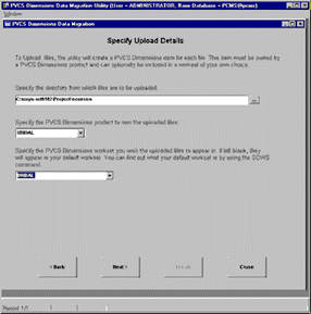
Select
the 'sources' directory that the XML files produced from the
UD6/CMtool driver are stored in (ours is c:\usys-ud6102\Project\sources),
as well as the project and work set created in previous steps.
Press Next to continue.

Press
OK to continue.
Specify
PVCS Dimensions Item Types and Design Parts

Delete
the entry for 'Filename pattern match' %, item format EXE.
For
each item format, select the item type as SRC. We used the
default design part of BRIDAL.AAAA.
Press
Next to continue.
Identify
Files that are NOT to be Transferred
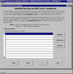
This
step is not used for loading XML sources into PVCS Dimensions.
Press
Next to continue.
Generate
Upload Script
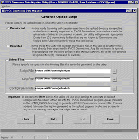
Select
the Unrestricted mode, and select suitable locations for the
script, log and configuration files.
Press
Next to continue.

Press
Continue to generate the script.
You
may be presented with another login dialog during the script
generation process.

Press
OK to proceed to uploading the script.
| |
Dimensions TeamLink Slave: Version
                          1.2.1 Dimensions

                          TeamLink Slave: Using Dimensions database PCMS_TOOL


                          Dimensions TeamLink Slave: 7622-Warning: No Resident


                          Software Definition found for node "ntora8i" Dimensions


                          TeamLink Slave: Using current Work Set BRIDAL:BRIDAL


                          Dimensions TeamLink Slave: Using C:\usys-ud6102\project\workset\
                          as the Work Set root directory Dimensions TeamLink

                          Slave: Reading configuration file '..\..\..\TEMP\upload.cfg'
|
Run
Upload Script
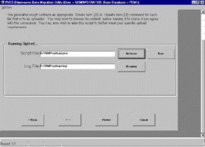
Press
RUN to execute the upload script.

Press
Continue to proceed to executing the script.
Running
Upload Script
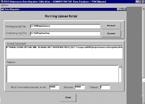
Close
when the RUN process has completed.
Press
FINISH to exit the data migration utility.
Taking
Control
| |
- |
Create
a Product |
|
|
- |
Define
file formats |
|
|
- |
Define
Object Types |
|
|
- |
Create
a Workset |
| |
- |
Setup
MULTIUSE |
| |
- |
Upload
sources |
|
Next >
|
- |
Create
Baseline |
Create
Baseline
To
create a baseline for the sources as imported initially into
version control, use the PVCS Dimensions PC Client Utility
pulldown menu File->New->Baseline.
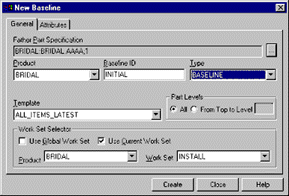
Select
to correct Father Design Part, and the Product, Baseline Type
and Workset, and name the baseline (we named ours INITIAL,
baseline type BASELINE).
Press
Create to create the baseline.
PVCS
Dimensions & UD6 guide
| |
- |
Configuration
Information |
| |
- |
Taking
Control in Dimensions |
|
Next >
|
- |
Releasing
a form using Dimensions |
| |
- |
Checking
a form in using Dimensions |
| |
- |
Adding
a form using Dimensions |
| |
- |
Finding
the difference in versions using Dimensions |
| |
- |
Problems
when using Dimensions |
Releasing
a form using PVCS Dimensions
NOTE: the user releasing / 'checking out' components from
the PVCS Dimensions Repository must have been assigned the
DEVELOPER role.
This
section assumes that you have set up your INUSE file(s), Uniface
Assignment file and MULTIUSE file as described in the article
Configure MULTIUSE.
Ensure
that you have created the network share and connected it to
h: and that you have created a directory h:\brd-aaa\.
When
you 'check out' a file from the PVCS Dimensions Repository,
using the Extract Item function from PC Client Utility, PVCS
Dimensions copies the file to a read-write area on your local
machine (or a network drive on the local machine).
At
the same time, UD6 MultiUSE updates the INUSE file for the
current PROJECT/VARIANT/USER to inform the UD6/CMtool driver
where the component now resides in the file system.
Once
set up this process is transparent to the user.
Let
us say that you are using the IDF and wish to make modifications
to the Application Start Up Shell ABASORG. You start up the
PVCS Client Utility, go into Workset Structure and select
Change Directory in the Work Set pulldown menu (the default
workset was set in a previous step).
Select
the directory h:\brd-aaa\.
From
the Work Set screen select the ABASORG.XML file in the applications
sub directory.
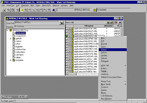
By
right clicking on the filename you can select 'Extract' (note:
Fetch will fetch a read-only copy, which may be useful for
viewing a previous version within the IDF).
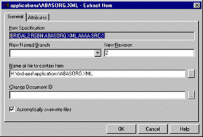
Note
the default directory for the checkout has already been set.
Press OK to continue.
When
you examine the directory h:\brd-aaa\ it will now contain
a directory 'applications', which contains the file ABASCAL.XML,
and the directory h:\ should have a new file called 'brd-aaaa.inuse'
(as specified in the USYS$UD6_PARAMS=LISTDIR h:\brd-aaaa.inuse
setting in the Uniface assignment file).
The
INUSE file will contain a single line, with both the original
and the new filenames for ABASCAL.XML.
Start
the IDF, and edit the application start-up shell that you
'checked out'. You should be able to make changes and store
them successfully. If you edit a component that you did NOT
check out. When you attempt to STORE your changes, you should
be presented with a message similar to:

If
you wish to, you can press OK, and then close the component
without saving, switch back to PVCS Dimensions and check out
this component. You now should be able to re-open the component
and make changes and store them.
PVCS
Dimensions & UD6 guide
| |
- |
Configuration
Information |
| |
- |
Taking
Control in Dimensions |
|
|
- |
Releasing
a form using Dimensions |
|
Next >
|
- |
Checking
a form in using Dimensions |
| |
- |
Adding
a form using Dimensions |
| |
- |
Finding
the difference in versions using Dimensions |
| |
- |
Problems
when using Dimensions |
Checking
a form in using PVCS Dimensions
NOTE:
the user 'checking in' components to the PVCS Dimensions Repository
must have been assigned the DEVELOPER role..
Now
that we have our new copy of the application start up shell
ABASCAL, you may make changes to it (remember that the source
files in the reference area are read-only). Add a comment
to the application shell.
From
the Work Set screen of the PC Client Utility select the ABASORG.XML
file in the applications sub directory.
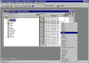
By
right clicking on the filename you can select 'Return'.
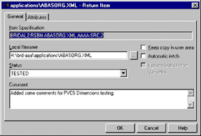
Enter a descriptive comment about the change, and select the
new status of the component.
Neither
the automatic fetch or keep item check boxes should be selected.
Press
OK to continue.
PVCS
Dimensions may give an error because UD6/CMtool driver has
cached a read-only open connection to the file.
To
resolve this, use the SQL workbench function from the Uniface
IDF to send the CLEANMMF command (data path UD6) to the UD6/CMtool
Driver. This will close all currently cached file connections.
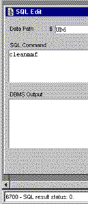
Once
this step is completed you should be able to check the file
into PVCS Dimensions as described above. If the problem persists,
it is probably due to the IDF not having committed the changes
correctly to the UD6/CMtool driver. In this case, open a different
form, then perform the CMEANMMF command from the SQL workbench
again.
Start
the IDF, and edit one the components that you 'checked in'.
When you attempt to STORE your changes, you should be presented
with a message similar to:

PVCS
Dimensions & UD6 guide
| |
- |
Configuration
Information |
| |
- |
Taking
Control in Dimensions |
|
|
- |
Releasing
a form using Dimensions |
|
|
- |
Checking
a form in using Dimensions |
|
Next >
|
- |
Adding
a form using Dimensions |
| |
- |
Finding
the difference in versions using Dimensions |
| |
- |
Problems
when using Dimensions |
Adding
a form using PVCS Dimensions
NOTE:
the user 'checking in' and adding components to the PVCS Dimensions
Repository must have been assigned the DEVELOPER role.
Creating
a brand new form / service / report that has never existed
before is a special case in a Configuration Managed environment.
When Uniface is using the UD6/CMtool Driver it will always
assume that if a 'file' does not exist in the 'reference area',
then it does not exist.
This
also applies to a new table / sub-type / library etc, but
not a new register, field etc since these exist 'within' an
existing entity (file).
So
the easiest way to create a new form, is to copy an existing
form file, remove its contents apart from the header and footer,
check it in to PVCS Dimensions and then check it out and use
it as normal.
e.g.:
h:\brd-aaa\components\New.xml contains:
| |
<?xml version="1.0"?>

                          <?xml-stylesheet href="components.xsl"
                          type="text/xsl"?>

                          <?xml-stylesheet href="components.css"
                          type="text/css"?>

                          <uniface_schema xmlns:html="http://www.w3.org/TR/REC-html40"
                          xmlns="componentsSchema.xml">

                          </uniface_schema>
|
PVCS
Dimensions simplifies this process, by allowing you to register
this file as a template to be used whenever a file is to be
created in future.
Create
an Item format template by taking an existing form component
and removing all of the lines between the <uniface_schema>
and </uniface_schema> tags. Please see the example above,
taking care to ensure that both tags are on separate lines.
Register
this file as the Item format template for XML files using
the Process Modeller.

Select
the Project, and Object Type Definiitions and press Next.
Select
the Object Type Definitions option then press next.

Select
the SRC Type name and press the Templates... button.
Press
the Add button to add the template.
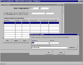
Enter
the Template name (we used XML) and revision 1, and the location
of the XML file that you created (we stored ours in d:\temp\ud6.xml).
Press
OK and then press the 'Set Default' button to assign this
as the default file format for SRC files.

Press
YES to continue.
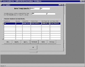
Press
OK when all details are complete
Exit
the process modeller by pressing Prev and then Exit.
Now
for all future users, when a file is created, it will automatically
be in the correct format.
You
can try it from the Work Set screen of the PC Client Utility
by selecting the components sub directory.
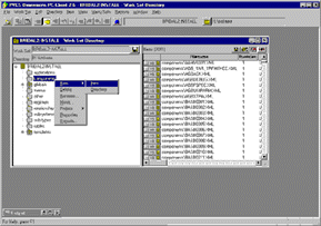
By
right clicking on the directory name you can select 'New->Item'.
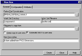
Select
the Father part specification, Automatic fetch to user area,
and enter a description and filename (our filename is testfrm.XML,
make sure you specify the .XML extension). The filename will
be the same as the Uniface component name.
Select
the Configuration tab...
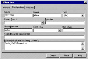
And
select the Item Type as SRC. You should also enter a descriptive
Reason.
Press
Create when complete.

Press
OK, and check that the file has been created in h:\brd-aaa\components\testfrm.xml.
It
should contain the template which you defined earlier (if
not copy the contents manually into it).
When
you start the IDF you WILL NOT see a component with this name,
however if you create one within the IDF in the usual manner,
then it will be stored in this file.
If
you attempt to create a component within the IDF without first
extracting one of that name into the work area, then you will
get a STORE error.
PVCS
Dimensions & UD6 guide
| |
- |
Configuration
Information |
| |
- |
Taking
Control in Dimensions |
|
|
- |
Releasing
a form using Dimensions |
|
|
- |
Checking
a form in using Dimensions |
|
|
- |
Adding
a form using Dimensions |
|
Next >
|
- |
Finding
the difference in versions using Dimensions |
| |
- |
Problems
when using Dimensions |
Finding
the difference in versions using PVCS Dimensions
One
of the most powerful features of a CM tool is it allows you
to find out WHO made WHAT change. PVCS Dimensions includes
a diff function to assist with this task.
From
the Work Set screen of the PC Client Utility select the ABASORG.XML
file in the applications sub directory.
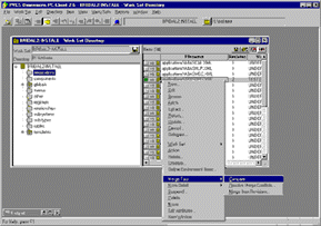
To
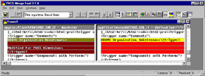
get to the "Merge Tool" window, select a file from
the right click menu select 'Merge Tool->Compare'.
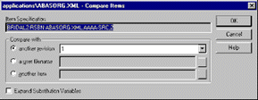
You
can compare the current workfile, to a version in the archive,
or two archived versions. Once you have made your selection
and pressed OK the "Merge Tool" Window is displayed
showing differences line by line.
Consult
the PVCS Dimensions reference manual for further information.
PVCS
Dimensions & UD6 guide
| |
- |
Configuration
Information |
| |
- |
Taking
Control in Dimensions |
|
|
- |
Releasing
a form using Dimensions |
|
|
- |
Checking
a form in using Dimensions |
|
|
- |
Adding
a form using Dimensions |
|
|
- |
Finding
the difference in versions using Dimensions |
|
Next >
|
- |
Problems
when using Dimensions |
Problems
when using PVCS Dimensions
PVCS
Dimensions does not support scriptable triggers
Most Version Control systems support some ability to execute
programs or scripts when certain events are 'triggered' in
the Version Control System.
PVCS
Dimensions supports this concept by a user replaceable DLL
file in the PCMS_ROOT\prog directory.
March
Hare supply a sample file for supporting the MultiUSE facility
as described in the article Configure MULTIUSE,
and also in the article UD6/MultiUSE
in the help file that comes with the driver.
|


